27/09/2023 NORD Gear (UK) Ltd
27/09/2023 CC-Link Partner Association Europe (CLPA Europe) Geared Dc Motor
Stepper motors are often perceived as more complex to specify and control compared to BLDC or brushed DC motors. However, their inherent positioning capability, converting electrical pulses to discrete ‘steps’, enables reliable incremental motion. Without the need for an external feedback device, this also aids simpler, and more compact, motion system design.
Matthieu Bouat, Application Engineer at Portescap, explains the key aspects of stepper motor specification.
A characteristic of the stepper motor design is that it remains in a given position as long as the current is maintained. This makes it ideal when incremental angular motion control is required, as the position of the rotor is known, based on the number of steps commanded by the drive. It can also achieve this without the cost, or footprint, of an encoder.
Can-stack stepper motors are based on permanent magnets and provide accuracy and torque sufficient for many motion applications, such as clinical diagnostics and valves. This design can also be converted to linear motion for applications such as a syringe pump and electronic pipettes. Alternatively, disc magnet stepper motors enable finer step resolutions, higher acceleration, and greater top speed. These motors are ideal for applications such as drug delivery systems that require exact volume dispensing.
Whichever type of stepper motor is required, it’s critical to understand the applied load characteristics to ensure the motor is sufficiently powerful to maintain its position. The motor must also be specified according to the wider application requirements.
Intrinsic parameters ensure that design characteristics are compatible with the application’s performance requirements. Steps per revolution is a fundamental basis and this can be calculated by multiplying the number of motor phases by the number of pole pairs. In connection, clarifying the step angle informs the angular rotation during one full step, while rotor inertia impacts dynamic motion.
Electrical parameters are useful to select the driver, and this includes resistance, nominal current, and voltage. Like any motor, it’s also important to identify thermal limitations that impact performance.
As well as providing rotational movement, stepper motors can produce torque in static mode, enabling them to be used as positioning devices. The crucial requirement is holding torque, the maximum static torque generated by the motor when energised at a nominal current. Static torque can be measured by energizing a phase at the rated current, and then progressively loading the motor until it loses step.
Alternatively, detent torque can hold motor position without energising the motor. This is achieved through the attractive forces between the magnets in the motor’s rotor and stator. This mode saves energy but cannot be used alone to maximise performance.
To optimise static mode, the absolute accuracy per full step must also be identified. Presented as a percentage of the full step angle, accuracy depends on parameters including friction and torque distortion due to detent torque.
During rotational movement in open loop operation, one pulse generates one step or micro step, and pulse frequency represents motor speed. To ensure control accuracy and maintain step, load torque cannot be exceeded. Crucially, pull-out torque, the maximum torque the motor can deliver at a given speed, must be known. This rating should be provided by the manufacturer, and as a guide, a 30% safety margin of the maximum load torque should be allowed.
In contrast, for pull-in torque, the maximum torque load that can be applied to the motor when starting at a given step frequency, there is no acceleration ramp. Instead, pull-in torque is measured by confirming the highest speed at which the motor can start. The manufacturer should be able to assist with the rating, but again, a safety margin of 30% should be allowed.
For dynamic operation, it's also crucial to identify the natural resonance frequency, the point at which the motor will lose stability. After each step, the rotor oscillates and normally stabilises at the target angular position. When operating the motor close to resonance frequency there is a risk of losing steps.
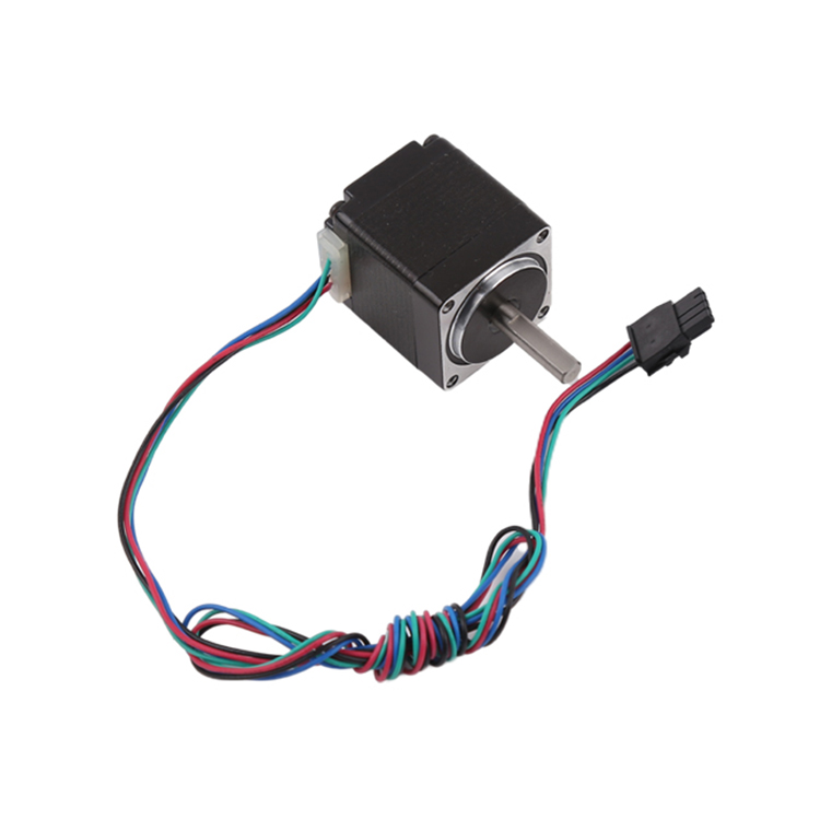
Stepper motors have advantages in repeatable accuracy and, as they don’t require external feedback devices, they are cost-effective. While they can be more complex to specify than BLDC or brushed motors, this can be achieved with a clear understanding of the necessary parameters. Portescap’s motion system engineers work with OEMs to identify the specification and can design the stepper motor solution to best suit application characteristics.
Image 1: Portescap’s motion system engineers work with OEMs to identify the specification and can design the stepper motor solution to best suit application characteristics.
Read more Portescap articles on the DMA News Portal
For more information, please contact: Portescap SA Rue Jardiniere 157 CH 2300 La Chaux-de-Fonds Switzerland Tel: +41 32 925 62 40 Email: Nicole.Monaco@portescap.com Web: https://www.portescap.com
Belden Launches Solutions to Enable Device Commissioning and Provide Advanced Cybersecurity
Process and Control Today are not responsible for the content of submitted or externally produced articles and images. Click here to email us about any errors or omissions contained within this article.
Sign-up for our weekly eNewsletter
Advertise with us | Media pack
Stepper Motor Gear © Copyright 1999-2023 Process and Control Today Ltd Registered in England No. 3733110 - studio44