Uploading a CAD file
The following section will explain how to prepare and upload a CAD file into the MapAble spatial database.
There are currently a whole range of CAD software available and lots of companies use different versions. In order to share data between these software packages, some standard formats are used. For 2D design spaces, people generally use .DXF, DGN and .DWG file formats. MapAble also standardised on these three formats.
CAD data organization
Computer-aided design (CAD) data is a file-based data source. You can connect directly to CAD files on the fly and manage them as read-only datasets without using conversion tools.
CAD data is organized into a schema comprising five generic feature classes: annotation, multipatch, point, polygon, and polyline.
CAD properties and attribution
The attribute table for each CAD feature class is a virtual table that exposes property values for geometry, layers, text, and user-defined attributes contained in the CAD file. Once the file is imported in MapAble, the field values can be queried, used as filtering criteria for visualization tasks, and computed as feature data.
Coordinate systems
X,y coordinates are geo-referenced with a geographic or projected coordinate system. A geographic coordinate system (GCS) is defined by a datum, an angular unit of measure (usually degrees), and a prime meridian. A projected coordinate system (PCS) consists of a linear unit of measure (usually meters or feet), a map projection, the specific parameters used by the map projection, and a geographic coordinate system.
A projected or geographic coordinate system can have a vertical coordinate system as an optional property. A vertical coordinate system (VCS) geo-references z-values, most commonly used to denote elevation. MapAble does however not render 3D data and z-values are only used to denote elevation for analytical purposes.
Widely used South African Map Projections
Gauss Conform Coordinate System
The Gauss Conform Coordinate System (as used in South Africa) uses the Transverse Mercator map projection formulae modified to produce westings (y) and southings (x) instead of northings (N) and eastings (E). Note that the Gauss Conform projection is used in the southern hemisphere only. This projection is used for the computation of the plane westings (yLo) and southings (xLo) coordinates, commonly (but incorrectly) known as the “Lo coordinate system".
Albers equal-area conic
The Albers equal-area conic projection, or Albers projection (named after Heinrich C. Albers), is a conic, equal area map projection that uses two standard parallels. Although scale and shape are not preserved, distortion is minimal between the standard parallels.
Transverse Mercator
The Transverse Mercator projection, in its various forms, is the most widely used projected coordinate system for world topographical and offshore mapping. All versions (e.g. Gauss Conform, Gauss Kruger, and Universal Transverse Mercator) have the same basic characteristics and formulas. The differences which distinguish the different forms of the projection, and which are applied in different countries arise from variations in the choice of the coordinate transformation parameters, namely the latitude of the origin, the longitude of the origin (central meridian), the scale factor at the origin (on the central meridian), and the values of false easting and false northing, which embody the units of measurement, given to the origin.
The suggested workflow for preparing a CAD file for upload is explained in the following diagram:
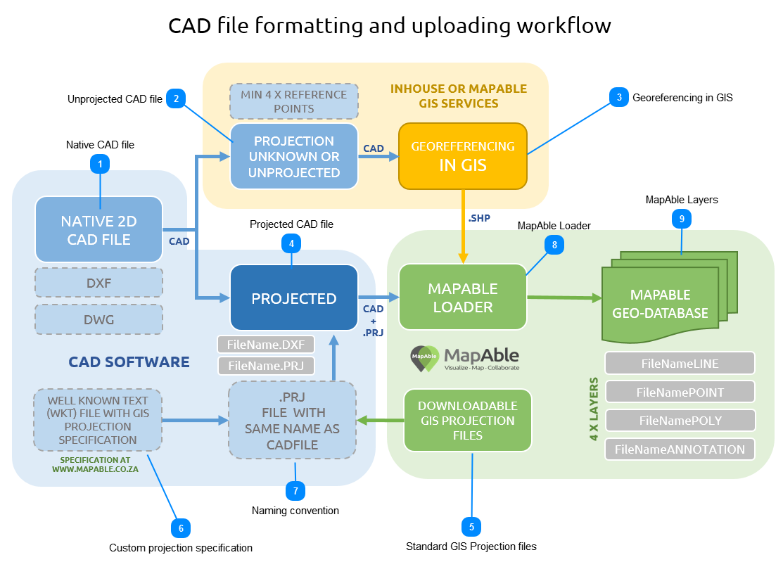
<TODO>: Insert description text here... And don't forget to add keyword for this topic
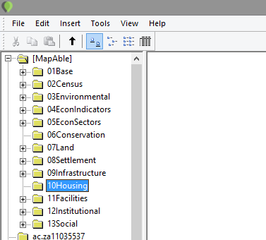
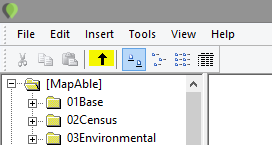
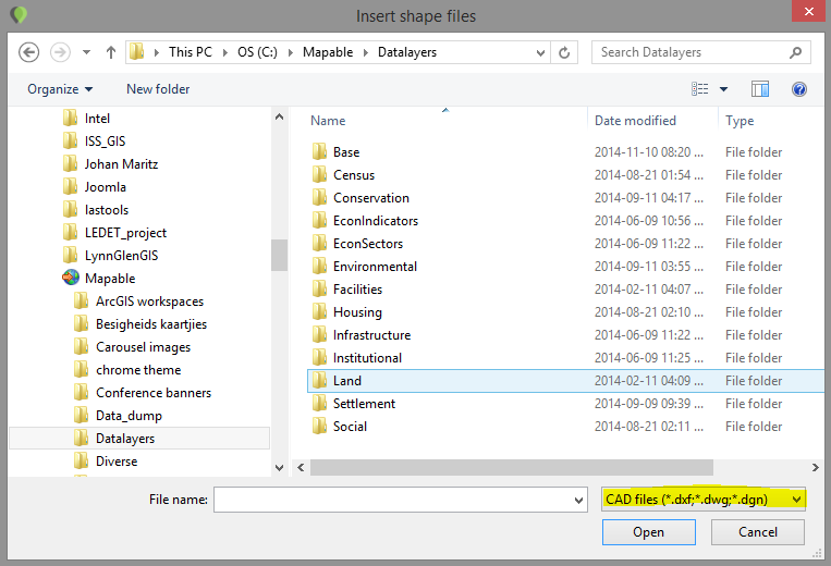
MapAble LayersTo access the data, please refer to Content>Add a layer section by clicking here
|